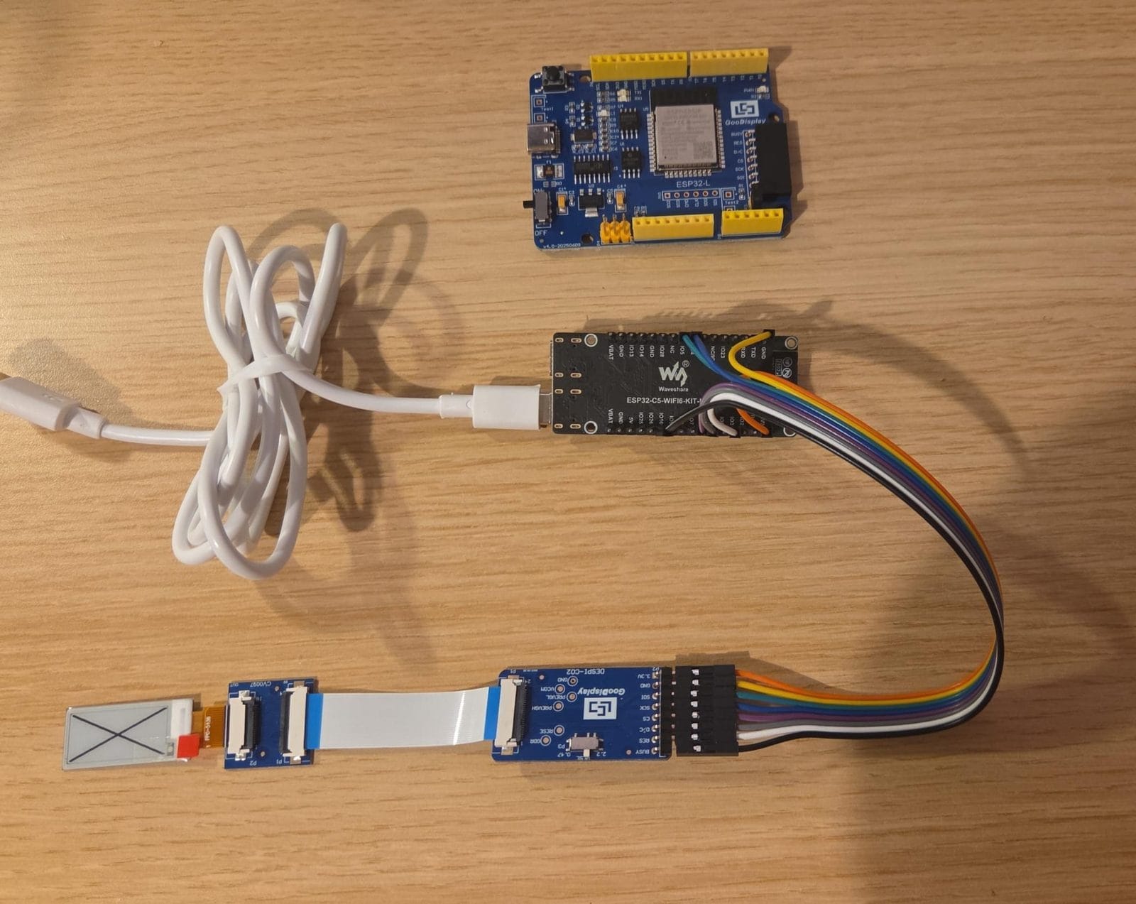
Two days blaming a booster circuit, two e-paper panels and an adapter board. The actual bug was one line of Rust that returned Ok(()) while doing nothing.
The product is an RF device. Its status UI was heading toward a cramped LED bar — a handful of blinking codes for a device with a lot to say. An e-paper panel is the experiment: same power budget, actual words. Bi-stable, so it costs nothing to keep an image up.
The panel is a Good Display GDEM0097T61, 0.97”, 184×88, SSD1680 controller, on their DESPI-C02 adapter. The target is an ESP32-C5.
Rust from the start, deliberately. Fast test cycles off-target, predictable performance, and it holds up well under agentic coding — the type system catches the class of mistake an LLM makes most often. The driver is a no_std crate over embedded-hal traits, with esp-idf-hal on the ESP side.
The panel did nothing. Then it did something worse: mottled grey, stuck.
Two days of blaming the hardware
In order, I convinced myself the problem was:
- SPI signal integrity. 4 MHz down to 500 kHz. No change.
- DMA. The 2024-byte framebuffer write dwarfs everything else on the bus. Off, then on. No change.
- The controller. A forum thread suggested this panel is really a UC8175. I rewrote the driver against that command set. No change.
- The booster. The DESPI-C02 generates the ±18 V rails e-ink needs to move pixels. Out came the multimeter: PREVGH measured 3.3 V, sitting at the input, not boosting. That felt like proof — an instrument reading, not a guess. Dead adapter, surely.
- The RESE switch. That adapter selects the booster’s feedback resistor: 0.47 Ω for GDEW panels, 2.2 Ω for GDEM. Mine was on 2.2, correctly. So the switch contact must be faulty.
- The panels. Two GDEMs, both dark. A different panel (GDEW0215T12, UC8151D) worked on the same rig. Conclusion: defective GDEMs.
Every one of those was wrong, several stated with confidence.
The test that ended it
Good Display ships a dev kit — their own ESP32 board, their own Arduino sample. Late in the process, I finally flashed their unmodified sketch: their MCU, their code, their adapter, my supposedly dead panel.
It ran the full demo. Logo, fast update, 4-grey image, a partial-refresh clock ticking to 00:05.
Panel fine. Adapter fine. Booster fine. Switch fine. Two days of hardware theory gone in ninety seconds — and now a known-good reference on the same wires.
Next: my Rust on their board. Same panel, same adapter, same pins, only the firmware differs. It hung waiting for BUSY to go idle. BUSY never went low. Not after a reset pulse, not after eight, not after holding RES low for a full second.
That last one is the tell. A panel held in reset cannot keep asserting BUSY — unless it isn’t being held in reset at all.
gpio_get_level() doesn’t lie
I stopped trusting the abstraction and asked the chip what its pads were doing:
// gpio_get_level() reads the real pad state, not what the HAL thinks it wrote.
let _ = epd.reset_low();
log::info!("RES low  -> pad12={} pad13(busy)={}", lv(12), lv(13));
let _ = epd.reset_high();
log::info!("RES high -> pad12={} pad13(busy)={}", lv(12), lv(13));
RES low -> pad12=0 pad13(busy)=1
RES high -> pad12=0 pad13(busy)=1Drive the reset pin high, the pad reads 0. Both times.
PinDriver::output(gpio12) had succeeded. Every set_high() returned Ok(()). The pin had never moved. The panel had been in permanent hardware reset since first boot — which is why BUSY never cleared, why reset pulses did nothing, and why a software reset command was ignored. A chip in reset ignores you.
On the classic ESP32, GPIO12 is MTDI — part of the JTAG block, and the flash-voltage strapping pin. It boots owned by that peripheral function. Arduino’s pinMode() releases that ownership. esp-idf-hal does not, and reports success anyway.
// Free the pad from JTAG/RTC ownership before PinDriver touches it.
rtc_gpio_deinit(12);
gpio_reset_pin(12);
gpio_set_direction(12, GPIO_MODE_OUTPUT);
BUSY started tracking reset immediately. Init succeeded first attempt. The panel drew.
Not just the reset line, either. GPIO14 is MTMS, and the data/command pin was on it — also stuck low, so every byte went out as a command and none as pixel data. That’s why an earlier build reported a clean init and showed a blank screen. Two pins, two silent failures, one cause.
This also explains the multimeter. PREVGH really was at 3.3 V; the meter was right. A controller held in reset never runs its charge pump, so the missing boost was a symptom two steps downstream of the actual fault. The measurement was accurate and the inference was wrong, which is worse than no measurement at all — it bought false confidence and sent me looking at the adapter for another day.
Then again, on the target
Back on the C5, the same panel failed the same way. I had even left a comment in the source saying the C5’s pins were plain GPIO and needed no unlock.
On the ESP32-C5, GPIO2 is MTMS and GPIO3 is MTDI. The reset line was on GPIO3.
Same trap, different chip, walked into twice — because I asserted instead of measured. Same three calls, same result: patterns cycling.
Takeaways
Prove the pad moved. gpio_get_level() reads actual pad state and takes a minute to wire up. It would have skipped the entire hardware hunt.
Measure the input, not the consequence. A logic analyzer on RES, CS and BUSY would have shown a reset line that never toggled, in minutes. I didn’t have one on the bench, so I reached for the tool I did have — and a multimeter on a power rail can only show you an effect, never which of the three plausible causes produced it. Where an analyzer wasn’t available, gpio_get_level() turned out to be the free substitute: it probes the same signal the analyzer would, from the inside.
A Result reports what the API chose to check. Ok(()) meant “the register write executed”, not “the voltage changed”. Reasonable contract, terrible assumption.
Know which pins are strapping or JTAG pins before wiring. Classic ESP32: GPIO12–15. C5: GPIO2/3 plus the boot straps. If a control line lands there, budget for an unlock or move the wire.
Cross-check against the vendor stack early. We did the C++ bring-up on the prescribed board late. Doing it first would have cleared the hardware before I measured a single voltage.
On the vendor: Good Display’s English documentation is imperfect — the datasheet’s reference program is a copy-paste from a different 122×250 panel, and its BUSY-polarity note is inverted — but it is complete enough to work from, and the sample code is the real specification. Their hardware has been good to work with. The bug was mine: a pin that agreed to everything and did none of it.